Sunday, November 15, 2009

DOWRY LAW IN INDIA


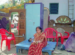
Payment of a dowry, gift—often financial, has a long history in many parts of the world. In India, the payment of a dowry was prohibited in 1961 under Indian civil law and subsequently by Sections 304B and 498a of the Indian Penal Code were enacted to make it easier for the wife to seek redress from potential harassment by the husband's family. Dowry laws has come under criticism that they are misused by women and their families.
Dowry or Dahej is the payment in cash or/and kind by the bride's family to the bridegroom' s family along with the giving away of the bride ( called Kanyadaan) in Indian marriage . Kanyadanam is an important part of Hindu marital rites. Kanya means daughter, and dana means gift.
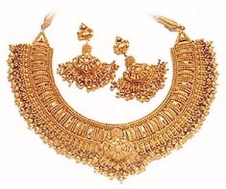
Dowry originated in upper caste families as the wedding gift to the bride from her family. The dowry was later given to help with marriage expenses and became a form of insurance in the case that her in-laws mistreated her. Although the dowry was legally prohibited in 1961, it continues to be highly institutionalized. The groom often demands a dowry consisting of a large sum of money, farm animals, furniture, and electronics.
The practice of dowry abuse is rising in India. The most severe in “bride burning”, the burning of women whose dowries were not considered sufficient by their husband or in-laws. Most of these incidents are reported as accidental burns in the kitchen or are disguised as suicide. It is evident that there exist deep rooted prejudices against women in India. Cultural practices such as the payment of dowry tend to subordinate women in Indian society.
Though prohibited by law in 1961, the extraction of DOWRY from the bride's family prior to marriage still occurs. When the dowry amount is not considered sufficient or is not forthcoming, the bride is often harassed, abused and made miserable. This abuse can escalate to the point where the husband or his family burn the bride, often by pouring kerosene on her and lighting it, usually killing her. The official records of these incidents are low because they are often reported as accidents or suicides by the family. In Delhi, a woman is burned to death almost every twelve hours . The number of dowry murders is increasing. In 1988, 2,209 women were killed in dowry related incidents and in 1990, 4,835 were killed . It is important to reiterate that these are official records, which are immensely under reported. The lack of official registration of this crime is apparent in Delhi, where ninety percent of cases of women burnt were recorded as accidents, five percent as suicide and only the remaining five percent were shown as murder .
According to Government figures there were a total of 5,377 dowry deaths in 1993, an increase of 12% from 1992. Despite the existence of rigorous laws to prevent dowry-deaths under a 1986 amendment to the Indian Penal Code (IPC), convictions are rare, and judges (usually men) are often uninterested and susceptible to bribery. Recent newspaper reports have focused on the alarming rate of deaths of married women in Hamirpur, Mandi and Bilaspur districts in the state of Himachal Pradesh.
It is true that a young man may require financial support to settle comfortably in his life and to fulfill other needs, but it should not be a reason to ask for dowry and to spoil the life of a girl if both the girl and boy are capable in all the ways to earn and settle with a comfortable life. Gifts that a girl gets from her parents home should solely be their wish and there should be no pressure to spend more while marrying their daughter. There are many instances when a wife commits suicide, because of her helplessness to tolerate the harassment for dowry. There are many instances when a wife is murdered because her parents were not able to give enough dowry. This murder is usually made like an accident. Stop violence against women! Legally, dowry is a banned practice in India but still happens all over the place. Many sensible and educated youths have gone against the idea of Dowry and they simply have a noble intention of marrying the without taking any money. Surprisingly, these days the ladies are themselves very much interested for huge amounts of dowry. Firstly the promise of all the marriage arrangements and then the huge amounts of dowry make the parents financially very weak and because of dowry system, people no longer prefer having a baby girl in India.
Dowry harassment

Dowry harassment is a criminal offence in India. Dowry harassment covers a span of behaviours and actions by the man, or his parents or other relatives. These are :

•the giving and taking of dowry.

•demanding dowry.
....which are offences under the Dowry Prohibition Act.
Apart from this there are offences related to dowry, like cruelty under Criminal Law (Section 498A, Indian Penal Code), which are:

•Cruelty which is so severe that it is likely to drive the woman to commit suicide.
•Cruelty which results in severe injury to the mental or physical health of the woman.
If your husband or any of his relatives are harassing you for dowry then depending on their behaviour they are guilty of any of the above offences.
Apart from you, your parents, or your relatives can also make a complaint of any of the above offences at a police station. There may also be a Dowry Prohibition officer in your city who you can get in touch with. Most of the major police stations in various cities in India also have a dowry prohibition cells or Crime Against Women cells, which can assist you.
Categories...

Is this dowry harassment?

Making a complaint of dowry harassment

Getting back what you gave in dowry

Gifts

Your Rights as a Wife or Your Conjugal Rights

Making a Demand for Dowry

Making a Police Case for Dowry Harassment

False Complaints of Dowry Harassment


Dowry Death

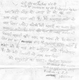
To curb the practice of dowry and harassment for dowry, special laws are made so that the investigation of dowry deaths are easier. The basic law is that if there is a death by burns or bodily injuries or under suspicious circumstances (like poisoning) of a woman within seven years of her marriage then her husband and his parents should be investigated for suspicion of dowry death first.
The presumption made by the police investigating and the court should be that the husband and his parents were responsible for the death of the woman, and then they have to establish that there was no harassment related to dowry.
This law was made because in a majority of such cases, the death is in connection to dowry.
Categories...

What is a dowry death

What you should do when there is a dowry death?

During a Case of Dowry Death

Special Powers of the Police and Magistrates


When the husband or his relatives pushed, convinced or helped the woman to commit suicide ..

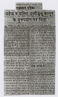
When any person convinces, pushes or helps another person to commit suicide, then it is a punishable offence and is known as abetment of suicide. But it has to be shown that the person actively intended to ensure that the person commit suicide.
Dowry harassment can sometimes be so severe and cruel that women have often committed suicide to escape the situation. In such situations it is only fair and just that the husband and his parents or other relatives who were harassing the woman for dowry should be held responsible for her suicide.
For this there is a special offence known as abetment of suicide. When there is severe harassment for dowry to the extent that the woman is pushed to commit suicide, then the husband and his parents can be held guilty of abetment to suicide.
The 1961 Dowry Prohibition Act
This act prohibits the request, payment or acceptance of a dowry, "as consideration for the marriage". where "dowry" is defined as a gift demanded or given as a precondition for a marriage. Gifts given without a precondition are not considered dowry, and are legal. Asking or giving of dowry can be punished by an imprisonment of up to six months, or a fine of up to Rs. 5000. It replaced several pieces of anti-dowry legislation that had been enacted by various Indian states.

IPC Section 304B

This Section of the Indian Penal Code was inserted by a 1986 amendment. The Dowry deaths law defines a 'dowry death' as the death of a woman caused by any burns or bodily injury or which does not occur under normal circumstances within seven years of her marriage. For a woman's death to be a dowry death, it must also be shown that soon before her death she was subjected to cruelty or harassment by her husband or any relative of her husband for, or in connection with, any demand for dowry. If this is proved, the woman's husband or relative is required to be deemed to have caused her death. Whoever commits dowry death is required to be punished with imprisonment for a term which shall not be less than seven years but which may extend to imprisonment for life.

IPC Section 498A

Section 498A was inserted into the penal code in 1983 it reads:
Whoever, being the husband or the relative of the husband of a woman, subjects such woman to cruelty shall be punished with imprisonment for a term which may extend to three years and shall also be liable to fine.
In practice, cruelty is taken to include the demanding of a dowry. This section is non-bailable, non-compoundable (i.e. it cannot be privately resolved between the parties concerned) and cognizable (i.e. the police can arrest the accused without investigation or warrants) on a report from a woman or close relative. Another examples of a cognizable law in India was the Prevention of Terrorist Activities Act.
Police often file charges against the husband, his parents and other relatives (whoever being named on the complaint by the wife or her close relatives) and put them in jail. There is no penalty (even a fine) for filing a false case. Many individuals have claimed this is being abused by the wife or her close relatives.
In urban India, the majority of families have inadequate knowledge regarding section 498A of the Indian Penal Code, 1860. The Malimath committee in 2003 proposed making amendments to this section although such amendments have been opposed by women's groups and radical feminists.
The Centre for Social Research India has released a research report opposing amendments to section 498A. According to this report, in the studied cases there were no convictions based solely on section 498A. Although the report states that 60.5 percent of the studied cases were falsified. They also state that many people believe the law has been abused by "educated and independent minded women." A police official asserted that in his district one-third of dowry murder cases were found totally false by the police. However, on December 17, 2003, the then Minister of State for Home Affairs, I.D. Swami said: “There is no information available with the Government to come to the conclusion that many families in India are suffering due to exaggerated allegations of harassment and dowry cases made by women against their husbands and other family members involving them in criminal misappropriation and cruelty.”
On 20 July 2005, Justices Arijit Pasayat and H.K. Seema of the Indian Supreme Court declared Section 498A to be constitutional."The object is to strike at the root of dowry menace. But by misuse of the provision a new legal terrorism can be unleashed. The provision is intended to be used as a shield and not an assassin's weapon. If [the] cry of "wolf" is made too often as a prank, assistance and protection may not be available when the actual wolf appears," the Bench said.
Several reports of the abuse of Section 498A have involved couples based outside India especially in the US. The United States Department of State has published the following travel warning:
A number of US men who have come to India to marry Indian nationals have been arrested and charged with crimes related to dowry extraction. Many of the charges stem from the US citizen’s inability to provide an immigrant visa for his prospective spouse to travel immediately to the United States.
The courts sometimes order the US citizen to pay large sums of money to his spouse in exchange for the dismissal of charges. The courts normally confiscate the American’s passport, and he must remain in India until the case has been settled.
It is stated in Travel Advisory by US, since the police may arrest anyone who is accused of committing a crime (even if the allegation is frivolous in nature), the Indian criminal justice system is often used to escalate personal disagreements into criminal charges. This practice has been increasingly exploited by dissatisfied business partners, contractors, estranged spouses, or other persons with whom the US citizen has a disagreement, occasionally resulting in the jailing of US citizens pending resolution of their disputes. At the very least, such circumstances can delay the US citizen's timely departure from India, and may result in an unintended long-term stay in the country. Corruption in India, especially at local levels, is a concern, as evidenced by Transparency International’s Corruption Perception Index of 3.5, ranking India in 72nd place of the world’s countries.
In a well publicized case, Dr. Balamurali Ambati, who earned his MD at age 17, and his family were detained in India for over three years in a suit related to alleged dowry demands by the family for his brother's wife Archana, which delayed Dr. Ambati's entry to the ophthalmology program for two years, leaving him to begin his residency in 1998. All charges against him were dismissed in October 1996 and all his family members were acquitted in June 1999.During the course of the trial the Ambatis produced a tape in which the father of Archana demanded US $500,000 to drop all the charges although the details of this particular case are still debated in India.
Another classical example of the gross misuse of Dowry Act (498A) is the case of television celebrity, [Suhaib Ilyasi]. India's Most Wanted television host was in controversy after the dispute over his daughter Aaliya's custody rose soon after Ilyasi's wife Anju committed suicide on January 10, 2000 in Delhi. While his mother–in-law,Rukma Singh wanted custody of the child on the ground that she had the right under Muslim law, Ilyasi had taken the plea that his marriage with Anju was not solemnized as per the Muslim law but had been a civil affair. His sister-in-law Rashmi Singh came from Canada six months after her sister's death and filed a complaint with the police against Ilyasi, alleging that he used to torture his wife Anju for dowry.
The case took a bizarre turn when Anju's brother Prashant Singh and father Prof K. P. Singh took a diametrically opposite stand and described the allegations against Ilyasi as ``rubbish. Prashant told Express Newsline:`whatever my mother and sister Rashmi are stating against Suhaib Ilyasi is a lot of rubbish. There is no truth in their statement or in the charges filed by the police against Suhaib. If you are holding Suhaib responsible for Anju's suicide, then my mother and sister are also to blame, as they unduly interfered in their family matters.'
K. P. Singh, a retired IIT professor, agreed with Prashant. “My wife and daughter are breaking up my family”. Both Anju's father and brother allege that Rukma and Rashmi have given statements against Suhaib as `they wanted custody of baby Aaliya. When Ilyasi delayed that, they put him in trouble.'
Anju's mother Rukma Singh had changed her earlier statement given in January, 2000, in which she had stated that she did not suspect any foul play by Suhaib Ilyasi. However when Ilyasi refused to give custody of his daughter, she changed her statement and alleged dowry harassment against Ilyasi.
It has been alleged for long that Dowry Act (498a) in India is being consistently mis-used by clever women for extortion and blackmailing. The NCRB records suggest that during 2005-2006, 94% of the 498A, 304B cases filed by women or by her relatives were primarily to settle scores.
Section 498A in itself is, however, not meant to deal specifically with dowry -- it is commonly considered to be a 'dowry law' because domestic violence against a wife related to dowry demands is considered to be within the scope of 'cruelty' envisaged by the Section.

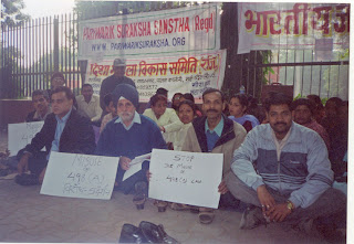
PROTEST AGAINST IPC 498A AND DOMESTIC VIOLENCE ACT at Jantar Mantar By Pariwar Suraksha


STATEMENT

We organized our first protest on Human Rights Day - 10th dec,05. It was a great success. Many families participated.
We have given several memorendums to The President, The P.M. and Mrs. Sonia Gandhi, among others in authorities. We are all so fed up of our lives being destroyed due to being implicated falsely in 498a cases. Cases under domestic violence act are being filed daily - it is time such draconian laws are reviewed .
The recently passed Domestic Violence Act is unfair, unbalanced, does not give opportunity to defend to the accused, is violative of fundamental rights of men. It must be withdrawn. According to our survey large percentage of women dont support it.
We are working to organize the biggest protest yet for maximum impact. We would like to continue the protest until our demands are met. Several memers are willing to even go on hunger strike.

...Deepak...
Thursday, October 8, 2009

GRAPHICS INTERCHANGE FORMAT


General Description.

The Graphics Interchange Format(sm) defines a protocol intended for the on-line transmission and interchange of raster graphic data in a way that is independent of the hardware used in their creation or display.

The Graphics Interchange Format is defined in terms of blocks and sub-blocks which contain relevant parameters and data used in the reproduction of a graphic. A GIF Data Stream is a sequence of protocol blocks and sub-blocks representing a collection of graphics. In general, the graphics in a Data Stream are assumed to be related to some degree, and to share some control information; it is recommended that encoders attempt to group together related graphics in order to minimize hardware changes during processing and to minimize control information overhead. For the same reason, unrelated graphics or graphics which require resetting hardware parameters should be encoded separately to the extent possible.

A Data Stream may originate locally, as when read from a file, or it may originate remotely, as when transmitted over a data communications line. The Format is defined with the assumption that an error-free Transport Level Protocol is used for communications; the Format makes no provisions for error-detection and error-correction.

The GIF Data Stream must be interpreted in context, that is, the application program must rely on information external to the Data Stream to invoke the decoder process.

Version Numbers

The version number in the Header of a Data Stream is intended to identify the minimum set of capabilities required of a decoder in order to fully process the Data Stream. An encoder should use the earliest possible version number that includes all the blocks used in the Data Stream. Within each block section in this document, there is an entry labeled Required Version which specifies the earliest version number that includes the corresponding block. The encoder should make every attempt to use the earliest version number covering all the blocks in the Data Stream; the unnecessary use of later version numbers will hinder processing by some decoders.

The Encoder

The Encoder is the program used to create a GIF Data Stream. From raster data and other information, the encoder produces the necessary control and data blocks needed for reproducing the original graphics.

The encoder has the following primary responsibilities.

Include in the Data Stream all the necessary information to reproduce the graphics.

Insure that a Data Stream is labeled with the earliest possible Version Number that will cover the definition of all the blocks in it; this is to ensure that the largest number of decoders can process the Data Stream.

Ensure encoding of the graphics in such a way that the decoding process is optimized. Avoid redundant information as much as possible.

To the extent possible, avoid grouping graphics which might require resetting hardware parameters during the decoding process.

Set to zero (off) each of the bits of each and every field designated as reserved. Note that some fields in the Logical Screen Descriptor and the Image Descriptor were reserved under Version 87a, but are used under version 89a.

The Decoder

The Decoder is the program used to process a GIF Data Stream. It processes the Data Stream sequentially, parsing the various blocks and sub-blocks, using the control information to set hardware and process parameters and interpreting the data to render the graphics.

The decoder has the following primary responsibilities.

Process each graphic in the Data Stream in sequence, without delays other than those specified in the control information.

Set its hardware parameters to fit, as closely as possible, the control information contained in the Data Stream.

Compliance

An encoder or a decoder is said to comply with a given version of the Graphics Interchange Format if and only if it fully conforms with and correctly implements the definition of the standard associated with that version. An encoder or a decoder may be compliant with a given version number and not compliant with some subsequent version.

About Recommendations

Each block section in this document contains an entry labeled Recommendation; this section lists a set of recommendations intended to guide and organize the use of the particular blocks. Such recommendations are geared towards making the functions of encoders and decoders more efficient, as well as making optimal use of the communications bandwidth. It is advised that these recommendations be followed.

About Color Tables

The GIF format utilizes color tables to render raster-based graphics. A color table can have one of two different scopes: global or local. A Global Color Table is used by all those graphics in the Data Stream which do not have a Local Color Table associated with them. The scope of the Global Color Table is the entire Data Stream. A Local Color Table is always associated with the graphic that immediately follows it; the scope of a Local Color Table is limited to that single graphic. A Local Color Table supersedes a Global Color Table, that is, if a Data Stream contains a Global Color Table, and an image has a Local Color Table associated with it, the decoder must save the Global Color Table, use the Local Color Table to render the image, and then restore the Global Color Table. Both types of color tables are optional, making it possible for a Data Stream to contain numerous graphics without a color table at all. For this reason, it is recommended that the decoder save the last Global Color Table used until another Global Color Table is encountered. In this way, a Data Stream which does not contain either a Global Color Table or a Local Color Table may be processed using the last Global Color Table saved. If a Global Color Table from a previous Stream is used, that table becomes the Global Color Table of the present Stream. This is intended to reduce the overhead incurred by color tables. In particular, it is recommended that an encoder use only one Global Color Table if all the images in related Data Streams can be rendered with the same table. If no color table is available at all, the decoder is free to use a system color table or a table of its own. In that case, the decoder may use a color table with as many colors as its hardware is able to support; it is recommended that such a table have black and white as its first two entries, so that monochrome images can be rendered adequately.

The Definition of the GIF Format allows for a Data Stream to contain only the Header, the Logical Screen Descriptor, a Global Color Table and the GIF Trailer. Such a Data Stream would be used to load a decoder with a Global Color Table, in preparation for subsequent Data Streams without a color table at all.

Blocks, Extensions and Scope

Blocks can be classified into three groups : Control, Graphic-Rendering and Special Purpose. Control blocks, such as the Header, the Logical Screen Descriptor, the Graphic Control Extension and the Trailer, contain information used to control the process of the Data Stream or information used in setting hardware parameters. Graphic-Rendering blocks such as the Image Descriptor and the Plain Text Extension contain information and data used to render a graphic on the display device. Special Purpose blocks such as the Comment Extension and the Application Extension are neither used to control the process of the Data Stream nor do they contain information or data used to render a graphic on the display device. With the exception of the Logical Screen Descriptor and the Global Color Table, whose scope is the entire Data Stream, all other Control blocks have a limited scope, restricted to the Graphic-Rendering block that follows them. Special Purpose blocks do not delimit the scope of any Control blocks; Special Purpose blocks are transparent to the decoding process. Graphic-Rendering blocks and extensions are used as scope delimiters for Control blocks and extensions. The labels used to identify labeled blocks fall into three ranges : 0x00-0x7F (0-127) are the Graphic Rendering blocks, excluding the Trailer (0x3B); 0x80-0xF9 (128-249) are the Control blocks; 0xFA-0xFF (250-255) are the Special Purpose blocks. These ranges are defined so that decoders can handle block scope by appropriately identifying block labels, even when the block itself cannot be processed.

Block Sizes

The Block Size field in a block, counts the number of bytes remaining in the block, not counting the Block Size field itself, and not counting the Block Terminator, if one is to follow. Blocks other than Data Blocks are intended to be of fixed length; the Block Size field is provided in order to facilitate skipping them, not to allow their size to change in the future. Data blocks and sub-blocks are of variable length to accommodate the amount of data.

Using GIF as an embedded protocol

As an embedded protocol, GIF may be part of larger application protocols, within which GIF is used to render graphics. In such a case, the application protocol could define a block within which the GIF Data Stream would be contained. The application program would then invoke a GIF decoder upon encountering a block of type GIF. This approach is recommended in favor of using Application Extensions, which become overhead for all other applications that do not process them. Because a GIF Data Stream must be processed in context, the application must rely on some means of identifying the GIF Data Stream outside of the Stream itself.

Data Sub-blocks

a. Description.

Data Sub-blocks are units containing data. They do not have a label, these blocks are processed in the context of control blocks, wherever data blocks are specified in the format. The first byte of the Data sub-block indicates the number of data bytes to follow. A data sub-block may contain from 0 to 255 data bytes. The size of the block does not account for the size byte itself, therefore, the empty sub-block is one whose size field contains 0x00.

b. Required Version
87a.

c. Syntax.
7 6 5 4 3 2 1 0 Field Name Type
+---------------+
0 | | Block Size Byte
+---------------+
1 | |
+- -+
2 | |
+- -+
3 | |
+- -+
| | Data Values Byte
+- -+
up | |
+- . . . . -+
to | |
+- -+
| |
+- -+
255 | |
+---------------+

Block Size - Number of bytes in the Data Sub-block; the size must be within 0 and 255 bytes, inclusive.
Data Values - Any 8-bit value. There must be exactly as many Data Values as specified by the Block Size field.

d. Extensions and Scope.
This type of block always occurs as part of a larger unit. It does not have a scope of itself.

e. Recommendation
None.

Block Terminator

a. Description.
This zero-length Data Sub-block is used to terminate a sequence of Data Sub-blocks. It contains a single byte in the position of the Block Size field and does not contain data.

b. Required Version
87a.

c. Syntax.
7 6 5 4 3 2 1 0 Field Name Type
+---------------+
0 | | Block Size Byte
+---------------+

Block Size - Number of bytes in the Data Sub-block; this field contains the fixed value 0x00.
Data Values - This block does not contain any data.

d. Extensions and Scope.

This block terminates the immediately preceding sequence of Data Sub-blocks. This block cannot be modified by any extension.

e. Recommendation
None.


Header

a. Description.
The Header identifies the GIF Data Stream in context. The Signature field marks the beginning of the Data Stream, and the Version field identifies the set of capabilities required of a decoder to fully process the Data Stream. This block is REQUIRED; exactly one Header must be present per Data Stream.

b. Required Version

Not applicable. This block is not subject to a version number. This block must appear at the beginning of every Data Stream.

c. Syntax.

7 6 5 4 3 2 1 0 Field Name Type
+---------------+
0 | | Signature 3 Bytes
+- -+
1 | |
+- -+
2 | |
+---------------+
3 | | Version 3 Bytes
+- -+
4 | |
+- -+
5 | |
+---------------+

Signature - Identifies the GIF Data Stream. This field contains the fixed value 'GIF'.
Version - Version number used to format the data stream. Identifies the minimum set of capabilities necessary to a decoder to fully process the contents of the Data Stream.
Version Numbers as of 10 July 1990 : "87a" - May 1987 "89a" - July 1989

Version numbers are ordered numerically increasing on the first two digits starting with 87 (87,88,...,99,00,...,85,86) and alphabetically increasing on the third character (a,...,z).

d. Extensions and Scope.

The scope of this block is the entire Data Stream. This block cannot be modified by any extension.

e. Recommendations

Signature - This field identifies the beginning of the GIF Data Stream; it is not intended to provide a unique signature for the identification of the data. It is recommended that the GIF Data Stream be identified externally by the application. (Refer to Appendix G for on-line identification of the GIF Data Stream.)

Version - ENCODER : An encoder should use the earliest possible version number that defines all the blocks used in the Data Stream. When two or more Data Streams are combined, the latest of the individual version numbers should be used for the resulting Data Stream. DECODER : A decoder should attempt to process the data stream to the best of its ability; if it encounters a version number which it is not capable of processing fully, it should nevertheless, attempt to process the data stream to the best of its ability, perhaps after warning the user that the data may be incomplete.

Logical Screen Descriptor

a. Description.

The Logical Screen Descriptor contains the parameters necessary to define the area of the display device within which the images will be rendered. The coordinates in this block are given with respect to the top-left corner of the virtual screen; they do not necessarily refer to absolute coordinates on the display device. This implies that they could refer to window coordinates in a window-based environment or printer coordinates when a printer is used. This block is REQUIRED; exactly one Logical Screen Descriptor must be present per Data Stream.

b. Required Version
Not applicable. This block is not subject to a version number. This block must appear immediately after the Header.

c. Syntax.

7 6 5 4 3 2 1 0 Field Name Type
+---------------+
0 | | Logical Screen Width Unsigned
+- -+
1 | |
+---------------+
2 | | Logical Screen Height Unsigned
+- -+
3 | |
+---------------+
4 | | | | | See below
+---------------+
5 | | Background Color Index Byte
+---------------+
6 | | Pixel Aspect Ratio Byte
+---------------+


= Global Color Table Flag 1 Bit
Color Resolution 3 Bits
Sort Flag 1 Bit
Size of Global Color Table 3 Bits

Logical Screen Width - Width, in pixels, of the Logical Screen where the images will be rendered in the displaying device.

Logical Screen Height - Height, in pixels, of the Logical Screen where the images will be rendered in the displaying device.

Global Color Table Flag - Flag indicating the presence of a Global Color Table; if the flag is set, the Global Color Table will immediately follow the Logical Screen Descriptor. This flag also selects the interpretation of the Background Color Index; if the flag is set, the value of the Background Color Index field should be used as the table index of the background color. (This field is the most significant bit of the byte.) Values : 0 - No Global Color Table follows, the Background Color Index field is meaningless. 1 - A Global Color Table will immediately follow, the Background Color Index field is meaningful.

Color Resolution - Number of bits per primary color available to the original image, minus 1. This value represents the size of the entire palette from which the colors in the graphic were selected, not the number of colors actually used in the graphic. For example, if the value in this field is 3, then the palette of the original image had 4 bits per primary color available to create the image. This value should be set to indicate the richness of the original palette, even if not every color from the whole palette is available on the source machine.

Sort Flag - Indicates whether the Global Color Table is sorted. If the flag is set, the Global Color Table is sorted, in order of decreasing importance. Typically, the order would be decreasing frequency, with most frequent color first. This assists a decoder, with fewer available colors, in choosing the best subset of colors; the decoder may use an initial segment of the table to render the graphic. Values : 0 - Not ordered. 1 - Ordered by decreasing importance, most important color first.

Size of Global Color Table - If the Global Color Table Flag is set to 1, the value in this field is used to calculate the number of bytes contained in the Global Color Table. To determine that actual size of the color table, raise 2 to [the value of the field + 1]. Even if there is no Global Color Table specified, set this field according to the above formula so that decoders can choose the best graphics mode to display the stream in. (This field is made up of the 3 least significant bits of the byte.)

Background Color Index - Index into the Global Color Table for the Background Color. The Background Color is the color used for those pixels on the screen that are not covered by an image. If the Global Color Table Flag is set to (zero), this field should be zero and should be ignored.

Pixel Aspect Ratio - Factor used to compute an approximation of the aspect ratio of the pixel in the original image. If the value of the field is not 0, this approximation of the aspect ratio is computed based on the formula: Aspect Ratio = (Pixel Aspect Ratio + 15) / 64 The Pixel Aspect Ratio is defined to be the quotient of the pixel's width over its height. The value range in this field allows specification of the widest pixel of 4:1 to the tallest pixel of 1:4 in increments of 1/64th. Values : 0 - No aspect ratio information is given. 1..255 - Value used in the computation.

d. Extensions and Scope.
The scope of this block is the entire Data Stream. This block cannot be modified by any extension.
e. Recommendations
None.

Global Color Table

a. Description.
This block contains a color table, which is a sequence of bytes representing red-green-blue color triplets. The Global Color Table is used by images without a Local Color Table and by Plain Text Extensions. Its presence is marked by the Global Color Table Flag being set to 1 in the Logical Screen Descriptor; if present, it immediately follows the Logical Screen Descriptor and contains a number of bytes equal to
3 × 2Size of Global Color Table+1.
This block is OPTIONAL; at most one Global Color Table may be present per Data Stream.

b. Required Version
87a

c. Syntax.
7 6 5 4 3 2 1 0 Field Name Type
+===============+
0 | | Red 0 Byte
+- -+
1 | | Green 0 Byte
+- -+
2 | | Blue 0 Byte
+- -+
3 | | Red 1 Byte
+- -+
| | Green 1 Byte
+- -+
up | |
+- . . . . -+ ...
to | |
+- -+
| | Green 255 Byte
+- -+
767 | | Blue 255 Byte
+===============+

d. Extensions and Scope.

The scope of this block is the entire Data Stream. This block cannot be modified by any extension.
e. Recommendation
None.

Image Descriptor

a. Description.
Each image in the Data Stream is composed of an Image Descriptor, an optional Local Color Table, and the image data. Each image must fit within the boundaries of the Logical Screen, as defined in the Logical Screen Descriptor. The Image Descriptor contains the parameters necessary to process a table based image. The coordinates given in this block refer to coordinates within the Logical Screen, and are given in pixels. This block is a Graphic-Rendering Block, optionally preceded by one or more Control blocks such as the Graphic Control Extension, and may be optionally followed by a Local Color Table; the Image Descriptor is always followed by the image data. This block is REQUIRED for an image. Exactly one Image Descriptor must be present per image in the Data Stream. An unlimited number of images may be present per Data Stream.

b. Required Version
87a.

c. Syntax.
7 6 5 4 3 2 1 0 Field Name Type
+---------------+
0 | | Image Separator Byte
+---------------+
1 | | Image Left Position Unsigned
+- -+
2 | |
+---------------+
3 | | Image Top Position Unsigned
+- -+
4 | |
+---------------+
5 | | Image Width Unsigned
+- -+
6 | |
+---------------+
7 | | Image Height Unsigned
+- -+
8 | |
+---------------+
9 | | | | | | See below
+---------------+

= Local Color Table Flag 1 Bit
Interlace Flag 1 Bit
Sort Flag 1 Bit
Reserved 2 Bits
Size of Local Color Table 3 Bits


Image Separator - Identifies the beginning of an Image Descriptor. This field contains the fixed value 0x2C.

Image Left Position - Column number, in pixels, of the left edge of the image, with respect to the left edge of the Logical Screen. Leftmost column of the Logical Screen is 0.

Image Top Position - Row number, in pixels, of the top edge of the image with respect to the top edge of the Logical Screen. Top row of the Logical Screen is 0.

Image Width - Width of the image in pixels.

Image Height - Height of the image in pixels.

Local Color Table Flag - Indicates the presence of a Local Color Table immediately following this Image Descriptor. (This field is the most significant bit of the byte.) Values : 0 - Local Color Table is not present. Use Global Color Table if available. 1 - Local Color Table present, and to follow immediately after this Image Descriptor.

Interlace Flag - Indicates if the image is interlaced. An image is interlaced in a four-pass interlace pattern; see Appendix E for details. Values : 0 - Image is not interlaced. 1 - Image is interlaced.

Sort Flag - Indicates whether the Local Color Table is sorted. If the flag is set, the Local Color Table is sorted, in order of decreasing importance. Typically, the order would be decreasing frequency, with most frequent color first. This assists a decoder, with fewer available colors, in choosing the best subset of colors; the decoder may use an initial segment of the table to render the graphic. Values : 0 - Not ordered. 1 - Ordered by decreasing importance, most important color first.

Size of Local Color Table - If the Local Color Table Flag is set to 1, the value in this field is used to calculate the number of bytes contained in the Local Color Table. To determine that actual size of the color table, raise 2 to the value of the field + 1. This value should be 0 if there is no Local Color Table specified. (This field is made up of the 3 least significant bits of the byte.)

d. Extensions and Scope.
The scope of this block is the Table-based Image Data Block that follows it. This block may be modified by the Graphic Control Extension.

e. Recommendation
None.

Local Color Table

a. Description.

This block contains a color table, which is a sequence of bytes representing red-green-blue color triplets. The Local Color Table is used by the image that immediately follows. Its presence is marked by the Local Color Table Flag being set to 1 in the Image Descriptor; if present, the Local Color Table immediately follows the Image Descriptor and contains a number of bytes equal to
3x2Size of Local Color Table+1.

If present, this color table temporarily becomes the active color table and the following image should be processed using it. This block is OPTIONAL; at most one Local Color Table may be present per Image Descriptor and its scope is the single image associated with the Image Descriptor that precedes it.

b. Required Version
87a.

c. Syntax.
7 6 5 4 3 2 1 0 Field Name Type
+===============+
0 | | Red 0 Byte
+- -+
1 | | Green 0 Byte
+- -+
2 | | Blue 0 Byte
+- -+
3 | | Red 1 Byte
+- -+
| | Green 1 Byte
+- -+
up | |
+- . . . . -+ ...
to | |
+- -+
| | Green 255 Byte
+- -+
767 | | Blue 255 Byte
+===============+

d. Extensions and Scope.

The scope of this block is the Table-based Image Data Block that immediately follows it. This block cannot be modified by any extension.
e. Recommendations
None.

Table Based Image Data

a. Description.

The image data for a table based image consists of a sequence of sub-blocks, of size at most 255 bytes each, containing an index into the active color table, for each pixel in the image. Pixel indices are in order of left to right and from top to bottom. Each index must be within the range of the size of the active color table, starting at 0. The sequence of indices is encoded using the LZW Algorithm with variable-length code, as described in Appendix F.

b. Required Version
87a.

c. Syntax.

The image data format is as follows:
7 6 5 4 3 2 1 0 Field Name Type
+---------------+
| | LZW Minimum Code Size Byte
+---------------+

+===============+
| |
/ / Image Data Data Sub-blocks
| |
+===============+

LZW Minimum Code Size. This byte determines the initial number of bits used for LZW codes in the image data, as described in Appendix F.
d. Extensions and Scope.
This block has no scope, it contains raster data. Extensions intended to modify a Table-based image must appear before the corresponding Image Descriptor.

e. Recommendations
None.

Graphic Control Extension

a. Description.

The Graphic Control Extension contains parameters used when processing a graphic rendering block. The scope of this extension is the first graphic rendering block to follow. The extension contains only one data sub-block. This block is OPTIONAL; at most one Graphic Control Extension may precede a graphic rendering block. This is the only limit to the number of Graphic Control Extensions that may be contained in a Data Stream.

b. Required Version
89a.

c. Syntax.
7 6 5 4 3 2 1 0 Field Name Type
+---------------+
0 | | Extension Introducer Byte
+---------------+
1 | | Graphic Control Label Byte
+---------------+

+---------------+
0 | | Block Size Byte
+---------------+
1 | | | | | See below
+---------------+
2 | | Delay Time Unsigned
+- -+
3 | |
+---------------+
4 | | Transparent Color Index Byte
+---------------+

+---------------+
0 | | Block Terminator Byte
+---------------+

= Reserved 3 Bits
Disposal Method 3 Bits
User Input Flag 1 Bit
Transparent Color Flag 1 Bit

Extension Introducer - Identifies the beginning of an extension block. This field contains the fixed value 0x21.

Graphic Control Label - Identifies the current block as a Graphic Control Extension. This field contains the fixed value 0xF9.

Block Size - Number of bytes in the block, after the Block Size field and up to but not including the Block Terminator. This field contains the fixed value 4.

Disposal Method - Indicates the way in which the graphic is to be treated after being displayed. Values : 0 - No disposal specified. The decoder is not required to take any action.
1 - Do not dispose. The graphic is to be left in place.
2 - Restore to background color. The area used by the graphic must be restored to the background color.
3 - Restore to previous. The decoder is required to restore the area overwritten by the graphic with what was there prior to rendering the graphic.
4-7 - To be defined.


User Input Flag - Indicates whether or not user input is expected before continuing. If the flag is set, processing will continue when user input is entered. The nature of the User input is determined by the application (Carriage Return, Mouse Button Click, etc.). Values : 0 - User input is not expected.
1 - User input is expected.
When a Delay Time is used and the User Input Flag is set, processing will continue when user input is received or when the delay time expires, whichever occurs first.

Transparency Flag - Indicates whether a transparency index is given in the Transparent Index field. (This field is the least significant bit of the byte.) Values : 0 - Transparent Index is not given.
1 - Transparent Index is given.


Delay Time - If not 0, this field specifies the number of hundredths (1/100) of a second to wait before continuing with the processing of the Data Stream. The clock starts ticking immediately after the graphic is rendered. This field may be used in conjunction with the User Input Flag field.

Transparency Index - The Transparency Index is such that when encountered, the corresponding pixel of the display device is not modified and processing goes on to the next pixel. The index is present if and only if the Transparency Flag is set to 1.

Block Terminator - This zero-length data block marks the end of the Graphic Control Extension.
d. Extensions and Scope.
The scope of this Extension is the graphic rendering block that follows it; it is possible for other extensions to be present between this block and its target. This block can modify the Image Descriptor Block and the Plain Text Extension.
e. Recommendations
Disposal Method - The mode Restore To Previous is intended to be used in small sections of the graphic; the use of this mode imposes severe demands on the decoder to store the section of the graphic that needs to be saved. For this reason, this mode should be used sparingly. This mode is not intended to save an entire graphic or large areas of a graphic; when this is the case, the encoder should make every attempt to make the sections of the graphic to be restored be separate graphics in the data stream. In the case where a decoder is not capable of saving an area of a graphic marked as Restore To Previous, it is recommended that a decoder restore to the background color.
User Input Flag - When the flag is set, indicating that user input is expected, the decoder may sound the bell (0x07) to alert the user that input is being expected. In the absence of a specified Delay Time, the decoder should wait for user input indefinitely. It is recommended that the encoder not set the User Input Flag without a Delay Time specified.

Comment Extension

a. Description.

The Comment Extension contains textual information which is not part of the actual graphics in the GIF Data Stream. It is suitable for including comments about the graphics, credits, descriptions or any other type of non-control and non-graphic data. The Comment Extension may be ignored by the decoder, or it may be saved for later processing; under no circumstances should a Comment Extension disrupt or interfere with the processing of the Data Stream. This block is OPTIONAL; any number of them may appear in the Data Stream.

b. Required Version
89a.

c. Syntax.
7 6 5 4 3 2 1 0 Field Name Type
+---------------+
0 | | Extension Introducer Byte
+---------------+
1 | | Comment Label Byte
+---------------+

+===============+
| |
N | | Comment Data Data Sub-blocks
| |
+===============+

+---------------+
0 | | Block Terminator Byte
+---------------+

Extension Introducer - Identifies the beginning of an extension block. This field contains the fixed value 0x21.
Comment Label - Identifies the block as a Comment Extension. This field contains the fixed value 0xFE.
Comment Data - Sequence of sub-blocks, each of size at most 255 bytes and at least 1 byte, with the size in a byte preceding the data. The end of the sequence is marked by the Block Terminator.
Block Terminator - This zero-length data block marks the end of the Comment Extension.

d. Extensions and Scope.

This block does not have scope. This block cannot be modified by any extension.

e. Recommendations

Data - This block is intended for humans. It should contain text using the 7-bit ASCII character set. This block should not be used to store control information for custom processing.
Position - This block may appear at any point in the Data Stream at which a block can begin; however, it is recommended that Comment Extensions do not interfere with Control or Data blocks; they should be located at the beginning or at the end of the Data Stream to the extent possible.

Plain Text Extension

a. Description.

The Plain Text Extension contains textual data and the parameters necessary to render that data as a graphic, in a simple form. The textual data will be encoded with the 7-bit printable ASCII characters. Text data are rendered using a grid of character cells defined by the parameters in the block fields. Each character is rendered in an individual cell. The textual data in this block is to be rendered as mono-spaced characters, one character per cell, with a best fitting font and size. For further information, see the section on Recommendations below. The data characters are taken sequentially from the data portion of the block and rendered within a cell, starting with the upper left cell in the grid and proceeding from left to right and from top to bottom. Text data is rendered until the end of data is reached or the character grid is filled. The Character Grid contains an integral number of cells; in the case that the cell dimensions do not allow for an integral number, fractional cells must be discarded; an encoder must be careful to specify the grid dimensions accurately so that this does not happen. This block requires a Global Color Table to be available; the colors used by this block reference the Global Color Table in the Stream if there is one, or the Global Color Table from a previous Stream, if one was saved. This block is a graphic rendering block, therefore it may be modified by a Graphic Control Extension. This block is OPTIONAL; any number of them may appear in the Data Stream.

b. Required Version
89a.

c. Syntax.
7 6 5 4 3 2 1 0 Field Name Type
+---------------+
0 | | Extension Introducer Byte
+---------------+
1 | | Plain Text Label Byte
+---------------+

+---------------+
0 | | Block Size Byte
+---------------+
1 | | Text Grid Left Position Unsigned
+- -+
2 | |
+---------------+
3 | | Text Grid Top Position Unsigned
+- -+
4 | |
+---------------+
5 | | Text Grid Width Unsigned
+- -+
6 | |
+---------------+
7 | | Text Grid Height Unsigned
+- -+
8 | |
+---------------+
9 | | Character Cell Width Byte
+---------------+
10 | | Character Cell Height Byte
+---------------+
11 | | Text Foreground Color Index Byte
+---------------+
12 | | Text Background Color Index Byte
+---------------+

+===============+
| |
N | | Plain Text Data Data Sub-blocks
| |
+===============+

+---------------+
0 | | Block Terminator Byte
+---------------+

Extension Introducer - Identifies the beginning of an extension block. This field contains the fixed value 0x21.
Plain Text Label - Identifies the current block as a Plain Text Extension. This field contains the fixed value 0x01.
Block Size - Number of bytes in the extension, after the Block Size field and up to but not including the beginning of the data portion. This field contains the fixed value 12.
Text Grid Left Position - Column number, in pixels, of the left edge of the text grid, with respect to the left edge of the Logical Screen.
Text Grid Top Position - Row number, in pixels, of the top edge of the text grid, with respect to the top edge of the Logical Screen.
Image Grid Width - Width of the text grid in pixels.
Image Grid Height - Height of the text grid in pixels.
Character Cell Width - Width, in pixels, of each cell in the grid.
Character Cell Height - Height, in pixels, of each cell in the grid.
Text Foreground Color Index - Index into the Global Color Table to be used to render the text foreground.
Text Background Color Index - Index into the Global Color Table to be used to render the text background.
Plain Text Data - Sequence of sub-blocks, each of size at most 255 bytes and at least 1 byte, with the size in a byte preceding the data. The end of the sequence is marked by the Block Terminator.
Block Terminator - This zero-length data block marks the end of the Plain Text Data Blocks.

d. Extensions and Scope.

The scope of this block is the Plain Text Data Block contained in it. This block may be modified by the Graphic Control Extension.

e. Recommendations

The data in the Plain Text Extension is assumed to be preformatted. The selection of font and size is left to the discretion of the decoder. If characters less than 0x20 or greater than 0xf7 are encountered, it is recommended that the decoder display a Space character (0x20). The encoder should use grid and cell dimensions such that an integral number of cells fit in the grid both horizontally as well as vertically. For broadest compatibility, character cell dimensions should be around 8x8 or 8x16 (width x height); consider an image for unusual sized text.

Application Extension

a. Description.

The Application Extension contains application-specific information; it conforms with the extension block syntax, as described below, and its block label is 0xFF.

b. Required Version
89a.

c. Syntax.
7 6 5 4 3 2 1 0 Field Name Type
+---------------+
0 | | Extension Introducer Byte
+---------------+
1 | | Extension Label Byte
+---------------+

+---------------+
0 | | Block Size Byte
+---------------+
1 | |
+- -+
2 | |
+- -+
3 | | Application Identifier 8 Bytes
+- -+
4 | |
+- -+
5 | |
+- -+
6 | |
+- -+
7 | |
+- -+
8 | |
+---------------+
9 | |
+- -+
10 | | Appl. Authentication Code 3 Bytes
+- -+
11 | |
+---------------+

+===============+
| |
| | Application Data Data Sub-blocks
| |
| |
+===============+

+---------------+
0 | | Block Terminator Byte
+---------------+

Extension Introducer - Defines this block as an extension. This field contains the fixed value 0x21.

Application Extension Label - Identifies the block as an Application Extension. This field contains the fixed value 0xFF.

Block Size - Number of bytes in this extension block, following the Block Size field, up to but not including the beginning of the Application Data. This field contains the fixed value 11.

Application Identifier - Sequence of eight printable ASCII characters used to identify the application owning the Application Extension.

Application Authentication Code - Sequence of three bytes used to authenticate the Application Identifier. An Application program may use an algorithm to compute a binary code that uniquely identifies it as the application owning the Application Extension.

d. Extensions and Scope.
This block does not have scope. This block cannot be modified by any extension.

e. Recommendation
None.

Trailer

a. Description.

This block is a single-field block indicating the end of the GIF Data Stream. It contains the fixed value 0x3B.

b. Required Version
87a.

c. Syntax.
7 6 5 4 3 2 1 0 Field Name Type
+---------------+
0 | | GIF Trailer Byte
+---------------+

d. Extensions and Scope.

This block does not have scope, it terminates the GIF Data Stream. This block may not be modified by any extension.

e. Recommendations
None.

Appendix A. Quick Reference Table.
Block Name Required Label Ext. Vers.
Application Extension Opt. (*) 0xFF (255) yes 89a
Comment Extension Opt. (*) 0xFE (254) yes 89a
Global Color Table Opt. (1) none no 87a
Graphic Control Extension Opt. (*) 0xF9 (249) yes 89a
Header Req. (1) none no N/A
Image Descriptor Opt. (*) 0x2C (044) no 87a (89a)
Local Color Table Opt. (*) none no 87a
Logical Screen Descriptor Req. (1) none no 87a (89a)
Plain Text Extension Opt. (*) 0x01 (001) yes 89a
Trailer Req. (1) 0x3B (059) no 87a

Unlabeled Blocks
Header Req. (1) none no N/A
Logical Screen Descriptor Req. (1) none no 87a (89a)
Global Color Table Opt. (1) none no 87a
Local Color Table Opt. (*) none no 87a

Graphic-Rendering Blocks
Plain Text Extension Opt. (*) 0x01 (001) yes 89a
Image Descriptor Opt. (*) 0x2C (044) no 87a (89a)

Control Blocks
Graphic Control Extension Opt. (*) 0xF9 (249) yes 89a

Special Purpose Blocks
Trailer Req. (1) 0x3B (059) no 87a
Comment Extension Opt. (*) 0xFE (254) yes 89a
Application Extension Opt. (*) 0xFF (255) yes 89a

legend: (1) if present, at most one occurrence
(*) zero or more occurrences
(+) one or more occurrences

Notes : The Header is not subject to Version Numbers.
(89a) The Logical Screen Descriptor and the Image Descriptor retained their
syntax from version 87a to version 89a, but some fields reserved under version
87a are used under version 89a.

Appendix B. GIF Grammar

A Grammar is a form of notation to represent the sequence in which certain objects form larger objects. A grammar is also used to represent the number of objects that can occur at a given position. The grammar given here represents the sequence of blocks that form the GIF Data Stream. A grammar is given by listing its rules. Each rule consists of the left-hand side, followed by some form of equals sign, followed by the right-hand side. In a rule, the right-hand side describes how the left-hand side is defined. The right-hand side consists of a sequence of entities, with the possible presence of special symbols. The following legend defines the symbols used in this grammar for GIF. Legend: <> grammar word
::= defines symbol
* zero or more occurrences
+ one or more occurrences
| alternate element [] optional element

Example:

::= Header * Trailer

This rule defines the entity as follows. It must begin with a Header. The Header is followed by an entity called Logical Screen, which is defined below by another rule. The Logical Screen is followed by the entity Data, which is also defined below by another rule. Finally, the entity Data is followed by the Trailer. Since there is no rule defining the Header or the Trailer, this means that these blocks are defined in the document. The entity Data has a special symbol (*) following it which means that, at this position, the entity Data may be repeated any number of times, including 0 times. For further reading on this subject, refer to a standard text on Programming Languages.

The Grammar.

::= Header * Trailer

::= Logical Screen Descriptor [Global Color Table]

::= |


::= [Graphic Control Extension]

::= |
Plain Text Extension

::= Image Descriptor [Local Color Table] Image Data

::= Application Extension |
Comment Extension


NOTE : The grammar indicates that it is possible for a GIF Data Stream to contain the Header, the Logical Screen Descriptor, a Global Color Table and the GIF Trailer. This special case is used to load a GIF decoder with a Global Color Table, in preparation for subsequent Data Streams without color tables at all.
Appendix C. Glossary
Active Color Table
Color table used to render the next graphic. If the next graphic is an image which has a Local Color Table associated with it, the active color table becomes the Local Color Table associated with that image. If the next graphic is an image without a Local Color Table, or a Plain Text Extension, the active color table is the Global Color Table associated with the Data Stream, if there is one; if there is no Global Color Table in the Data Stream, the active color table is a color table saved from a previous Data Stream, or one supplied by the decoder.
Block
Collection of bytes forming a protocol unit. In general, the term includes labeled and unlabeled blocks, as well as Extensions.
Data Stream
The GIF Data Stream is composed of blocks and sub-blocks representing images and graphics, together with control information to render them on a display device. All control and data blocks in the Data Stream must follow the Header and must precede the Trailer. (See the data stream grammar).
Decoder
A program capable of processing a GIF Data Stream to render the images and graphics contained in it.
Encoder
A program capable of capturing and formatting image and graphic raster data, following the definitions of the Graphics Interchange Format.
Extension
A protocol block labeled by the Extension Introducer 0x21.
Extension Introducer
Label (0x21) defining an Extension.

Graphic

Data which can be rendered on the screen by virtue of some algorithm. The term graphic is more general than the term image; in addition to images, the term graphic also includes data such as text, which is rendered using character bit-maps.

Image

Data representing a picture or a drawing; an image is represented by an array of pixels called the raster of the image.

Raster

Array of pixel values representing an image.
Appendix D. Conventions.
Animation - The Graphics Interchange Format is not intended as a platform for animation, even though it can be done in a limited way.

Byte Ordering - Unless otherwise stated, multi-byte numeric fields are ordered with the Least Significant Byte first.

Color Indices - Color indices always refer to the active color table, either the Global Color Table or the Local Color Table.

Color Order - Unless otherwise stated, all triple-component RGB color values are specified in Red-Green-Blue order.

Color Tables - Both color tables, the Global and the Local, are optional; if present, the Global Color Table is to be used with every image in the Data Stream for which a Local Color Table is not given; if present, a Local Color Table overrides the Global Color Table. However, if neither color table is present, the application program is free to use an arbitrary color table. If the graphics in several Data Streams are related and all use the same color table, an encoder could place the color table as the Global Color Table in the first Data Stream and leave subsequent Data Streams without a Global Color Table or any Local Color Tables; in this way, the overhead for the table is eliminated. It is recommended that the decoder save the previous Global Color Table to be used with the Data Stream that follows, in case it does not contain either a Global Color Table or any Local Color Tables. In general, this allows the application program to use past color tables, significantly reducing transmission overhead.

Extension Blocks - Extensions are defined using the Extension Introducer code to mark the beginning of the block, followed by a block label, identifying the type of extension. Extension Codes are numbers in the range from 0x00 to 0xFF, inclusive. Special purpose extensions are transparent to the decoder and may be omitted when transmitting the Data Stream on-line. The GIF capabilities dialogue makes the provision for the receiver to request the transmission of all blocks; the default state in this regard is no transmission of Special purpose blocks.

Reserved Fields - All Reserved Fields are expected to have each bit set to zero (off).

Appendix E. Interlaced Images.
The rows of an Interlaced images are arranged in the following order: Group 1 : Every 8th. row, starting with row 0. (Pass 1)
Group 2 : Every 8th. row, starting with row 4. (Pass 2)
Group 3 : Every 4th. row, starting with row 2. (Pass 3)
Group 4 : Every 2nd. row, starting with row 1. (Pass 4)

The Following example illustrates how the rows of an interlaced image are ordered.

Row Number Interlace Pass

0 ----------------------------------------- 1
1 ----------------------------------------- 4
2 ----------------------------------------- 3
3 ----------------------------------------- 4
4 ----------------------------------------- 2
5 ----------------------------------------- 4
6 ----------------------------------------- 3
7 ----------------------------------------- 4
8 ----------------------------------------- 1
9 ----------------------------------------- 4
10 ----------------------------------------- 3
11 ----------------------------------------- 4
12 ----------------------------------------- 2
13 ----------------------------------------- 4
14 ----------------------------------------- 3
15 ----------------------------------------- 4
16 ----------------------------------------- 1
17 ----------------------------------------- 4
18 ----------------------------------------- 3
19 ----------------------------------------- 4

Appendix F. Variable-Length-Code LZW Compression

The Variable-Length-Code LZW Compression is a variation of the Lempel-Ziv Compression algorithm in which variable-length codes are used to replace patterns detected in the original data. The algorithm uses a code or translation table constructed from the patterns encountered in the original data; each new pattern is entered into the table and its index is used to replace it in the compressed stream.

The compressor takes the data from the input stream and builds a code or translation table with the patterns as it encounters them; each new pattern is entered into the code table and its index is added to the output stream; when a pattern is encountered which had been detected since the last code table refresh, its index from the code table is put on the output stream, thus achieving the data compression. The expander takes input from the compressed data stream and builds the code or translation table from it; as the compressed data stream is processed, codes are used to index into the code table and the corresponding data is put on the decompressed output stream, thus achieving data decompression. The details of the algorithm are explained below. The Variable-Length-Code aspect of the algorithm is based on an initial code size (LZW-initial code size), which specifies the initial number of bits used for the compression codes. When the number of patterns detected by the compressor in the input stream exceeds the number of patterns encodable with the current number of bits, the number of bits per LZW code is increased by one.

The Raster Data stream that represents the actual output image can be represented as:

7 6 5 4 3 2 1 0
+---------------+
| LZW code size |
+---------------+

+---------------+ ----+
| block size | |
+---------------+ |
| | +-- Repeated as many
| data bytes | | times as necessary.
| | |
+---------------+ ----+

. . . . . . ------- The code that terminates the LZW
compressed data must appear before
Block Terminator.
+---------------+
|0 0 0 0 0 0 0 0| Block Terminator
+---------------+

The conversion of the image from a series of pixel values to a transmitted or stored character stream involves several steps. In brief these steps are:

Establish the Code Size - Define the number of bits needed to represent the actual data.

Compress the Data - Compress the series of image pixels to a series of compression codes.

Build a Series of Bytes - Take the set of compression codes and convert to a string of 8-bit bytes.

Package the Bytes - Package sets of bytes into blocks preceded by character counts and output.

ESTABLISH CODE SIZE

The first byte of the Compressed Data stream is a value indicating the minimum number of bits required to represent the set of actual pixel values. Normally this will be the same as the number of color bits. Because of some algorithmic constraints however, black & white images which have one color bit must be indicated as having a code size of 2. This code size value also implies that the compression codes must start out one bit longer.

COMPRESSION

The LZW algorithm converts a series of data values into a series of codes which may be raw values or a code designating a series of values. Using text characters as an analogy, the output code consists of a character or a code representing a string of characters. The LZW algorithm used in GIF matches algorithmically with the standard LZW algorithm with the following differences:

A special Clear code is defined which resets all compression/decompression parameters and tables to a start-up state. The value of this code is 2. For example if the code size indicated was 4 (image was 4 bits/pixel) the Clear code value would be 16 (10000 binary). The Clear code can appear at any point in the image data stream and therefore requires the LZW algorithm to process succeeding codes as if a new data stream was starting. Encoders should output a Clear code as the first code of each image data stream.

An End of Information code is defined that explicitly indicates the end of the image data stream. LZW processing terminates when this code is encountered. It must be the last code output by the encoder for an image. The value of this code is +1.

The first available compression code value is +2>.

The output codes are of variable length, starting at +1 bits per code, up to 12 bits per code. This defines a maximum code value of 4095 (0xFFF). Whenever the LZW code value would exceed the current code length, the code length is increased by one. The packing/unpacking of these codes must then be altered to reflect the new code length.

BUILD 8-BIT BYTES

Because the LZW compression used for GIF creates a series of variable length codes, of between 3 and 12 bits each, these codes must be reformed into a series of 8-bit bytes that will be the characters actually stored or transmitted. This provides additional compression of the image. The codes are formed into a stream of bits as if they were packed right to left and then picked off 8 bits at a time to be output.

Assuming a character array of 8 bits per character and using 5 bit codes to be packed, an example layout would be similar to:

+---------------+
0 | | bbbaaaaa
+---------------+
1 | | dcccccbb
+---------------+
2 | | eeeedddd
+---------------+
3 | | ggfffffe
+---------------+
4 | | hhhhhggg
+---------------+
. . .
+---------------+
N | |
+---------------+

Note that the physical packing arrangement will change as the number of bits per compression code change but the concept remains the same.

PACKAGE THE BYTES

Once the bytes have been created, they are grouped into blocks for output by preceding each block of 0 to 255 bytes with a character count byte. A block with a zero byte count terminates the Raster Data stream for a given image. These blocks are what are actually output for the GIF image. This block format has the side effect of allowing a decoding program the ability to read past the actual image data if necessary by reading block counts and then skipping over the data.

FURTHER READING

[1]
Ziv, J. and Lempel, A. : "A Universal Algorithm for Sequential Data Compression", IEEE Transactions on Information Theory, May 1977.
[2]
Welch, T. : "A Technique for High-Performance Data Compression", Computer, June 1984.
[3]
Nelson, M.R. : "LZW Data Compression", Dr. Dobb's Journal, October 1989.
Appendix G. On-line Capabilities Dialogue.
NOTE : This section is currently (10 July 1990) under revision; the information provided here should be used as general guidelines. Code written based on this information should be designed in a flexible way to accommodate any changes resulting from the revisions.

The following sequences are defined for use in mediating control between a GIF sender and GIF receiver over an interactive communications line. These sequences do not apply to applications that involve downloading of static GIF files and are not considered part of a GIF file.

GIF CAPABILITIES ENQUIRY

The GIF Capabilities Enquiry sequence is issued from a host and requests an interactive GIF decoder to return a response message that defines the graphics parameters for the decoder. This involves returning information about available screen sizes, number of bits/color supported and the amount of color detail supported. The escape sequence for the GIF Capabilities Enquiry is defined as:
ESC[>0g 0x1B 0x5B 0x3E 0x30 0x67

GIF CAPABILITIES RESPONSE

The GIF Capabilities Response message is returned by an interactive GIF decoder and defines the decoder's display capabilities for all graphics modes that are supported by the software. Note that this can also include graphics printers as well as a monitor screen. The general format of this message is:

#version;protocol{;dev, width, height, color-bits, color-res}...
'#' GIF Capabilities Response identifier character.
version GIF format version number; initially '87a'.
protocol='0' No end-to-end protocol supported by decoder Transfer as direct 8-bit data stream.
protocol='1' Can use CIS B+ error correction protocol to transfer GIF data interactively from the host directly to the display.
dev = '0' Screen parameter set follows.
dev = '1' Printer parameter set follows.
width Maximum supported display width in pixels.
height Maximum supported display height in pixels.
color-bits Number of bits per pixel supported. The number of supported colors is therefore 2**color-bits.
color-res Number of bits per color component supported in the hardware color palette. If color-res is '0' then no hardware palette table is available.

Note that all values in the GIF Capabilities Response are returned as ASCII decimal numbers and the message is terminated by a Carriage Return character.

The following GIF Capabilities Response message describes three standard IBM PC Enhanced Graphics Adapter configurations with no printer; the GIF data stream can be processed within an error correcting protocol:

#87a;1;0,320,200,4,0;0,640,200,2,2;0,640,350,4,2

ENTER GIF GRAPHICS MODE

Two sequences are currently defined to invoke an interactive GIF decoder into action. The only difference between them is that different output media are selected. These sequences are:
ESC[>1g Display GIF image on screen

0x1B 0x5B 0x3E 0x31 0x67

ESC[>2g Display image directly to an attached graphics printer. The image may optionally be displayed on the screen as well.

0x1B 0x5B 0x3E 0x32 0x67

Note that the 'g' character terminating each sequence is in lowercase.

INTERACTIVE ENVIRONMENT

The assumed environment for the transmission of GIF image data from an interactive application is a full 8-bit data stream from host to micro. All 256 character codes must be transferrable. The establishing of an 8-bit data path for communications will normally be taken care of by the host application programs. It is however up to the receiving communications programs supporting GIF to be able to receive and pass on all 256 8-bit codes to the GIF decoder software.

...Deepak...

Sunday, September 27, 2009

MOON WATER


The first object in the night sky most of us ever saw, the Moon remains a mystery. Haunted by poets, looked upon by youngsters in love, studied intensely by astronomers for four centuries, examined by geologists for the last 50 years, walked upon by twelve humans, this is Earth's satellite.

And as we look towards the Moon with thoughts of setting up a permanent home there, one new question is paramount: does the Moon have water? Although none has been definitely detected, recent evidence suggests that it's there.

Why should there be water on the Moon? Simply for the same reason that there's water on Earth. A favorite theory is that water, either as water by itself or as its components of hydrogen and oxygen, was deposited on Earth during its early history--mostly during a period of "late heavy bombardment" 3.9 billion years ago--by the impacts of comets and asteroids. Because the Moon shares the same area of space as Earth, it should have received its share of water as well. However, since it has only a tiny fraction of Earth's gravity, most of the Moon's water supply should have evaporated and drifted off into space long ago. Most, but perhaps not all.

In ancient times, observers commonly thought the Moon had abundant water--in fact, the great lava plains like Mare Imbrium were called maria, or seas. But when Neil Armstrong and Buzz Aldrin landed on the Moon in 1969, they stepped out not into the water of the Sea of Tranquillity, but onto basaltic rock. No one was surprised by that--the idea of lunar maria had been replaced by lava plains decades earlier.

As preparations were underway in the mid 1960s for the Apollo program, questions about water on the Moon were barely on the radar screen. Geologists and astronomers were divided at the time as to whether the lunar surface was a result of volcanic forces from beneath, or cosmic forces from above. Grove Carl Gilbert in 1893 already had the answer. That famous geologist suggested that large asteroidal objects hit the Moon, forming its craters. Ralph Baldwin articulated the same idea in 1949, and Gene Shoemaker revived the idea again around 1960. Shoemaker, almost alone among geologists of his day, saw the Moon as a fertile subject for field geology. He saw the craters on the Moon as logical impact sites that were formed not gradually in eons, but explosively in seconds.

The Apollo flights confirmed that the dominant geological process on the Moon is impact-related. That discovery, in turn, ushered in a new question: Since Earth's water was probably delivered largely by comets and asteroids, could this process have done the same for the Moon? And could some of that water still be there?

In 1994, the SDI-NASA Clementine spacecraft orbited the Moon and mapped its surface. In one experiment, Clementine beamed radio signals into shadowed craters near the Moon's south pole. The reflections, received by antennas on Earth, seemed to come from icy material.

That makes sense. If there is water on the Moon, it's probably hiding in the permanent shadows of deep, cold craters, safe from vaporizing sunlight, frozen solid.

So far so good, but... the Clementine data were not conclusive, and when astronomers tried to find ice in the same craters using the giant Arecibo radar in Puerto Rico, they couldn't. Maybe Clementine was somehow wrong.

In 1998, NASA sent another spacecraft, Lunar Prospector, to check. Using a device called a neutron spectrometer, Lunar Prospector scanned the Moon's surface for hydrogen-rich minerals. Once again, polar craters yielded an intriguing signal: neutron ratios indicated hydrogen. Could it be the "H" in H2O? Many researchers think so.

Lunar Prospector eventually sacrificed itself to the search. When the spacecraft's primary mission was finished, NASA decided to crash Prospector near the Moon's south pole, hoping to liberate a bit of its meager layer of water. Earth's satellite might briefly become a comet as amounts of water vapor were released.


Lunar Prospector crashed, as planned, and several teams of researchers tried to detect that cloud, but without success. Either there was no water, or there was not enough water to be detected by Earth-based telescopes, or the telescopes were not looking in precisely the right place. In any event, no water was found from Prospector's impact.

In 2008, NASA plans to send a new spacecraft to the Moon: the Lunar Reconnaissance Orbiter (LRO), bristling with advanced sensors that can sense water in at least four different ways. Scientists are hopeful that LRO can decide the question of Moon water once and for all.

Our interest is not just scientific. If we are indeed to build a base on the Moon, the presence of water already there would offer a tremendous advantage in building and running it. It's been 35 years since we first set foot on the Moon. Now ambitious eyes once again look toward our satellite not just as a place to visit, but as a place to live.


Since man first touched the moon and brought pieces of it back to Earth, scientists have thought that the lunar surface was bone dry. But new observations from three different spacecraft have put this notion to rest with what has been called "unambiguous evidence" of water across the surface of the moon.

The new findings, detailed in the Sept. 25 issue of the journal Science, come in the wake of further evidence of lunar polar water ice by NASA's Lunar Reconnaissance Orbiter and just weeks before the planned lunar impact of NASA's LCROSS satellite, which will hit one of the permanently shadowed craters at the moon's south pole in hope of churning up evidence of water ice deposits in the debris field.

The moon remains drier than any desert on Earth, but the water is said to exist on the moon in very small quantities. One ton of the top layer of the lunar surface would hold about 32 ounces of water, researchers said.

"If the water molecules are as mobile as we think they are — even a fraction of them — they provide a mechanism for getting water to those permanently shadowed craters," said planetary geologist Carle Pieters of Brown University in Rhode Island, who led one of the three studies in Science on the lunar find, in a statement. "This opens a whole new avenue [of lunar research], but we have to understand the physics of it to utilize it."

Finding water on the moon would be a boon to possible future lunar bases, acting as a potential source of drinking water and fuel.

Apollo turns up dry

When Apollo astronauts returned from the moon 40 years ago, they brought back several samples of lunar rocks.

The moon rocks were analyzed for signs of water bound to minerals present in the rocks; while trace amounts of water were detected, these were assumed to be contamination from Earth, because the containers the rocks came back in had leaked.

"The isotopes of oxygen that exist on the moon are the same as those that exist on Earth, so it was difficult if not impossible to tell the difference between water from the moon and water from Earth," said Larry Taylor of the University of Tennessee, Knoxville, who is a member of one of the NASA-built instrument teams for India's Chandrayaan-1 satellite and has studied the moon since the Apollo missions.

While scientists continued to suspect that water ice deposits could be found in the coldest spots of south pole craters that never saw sunlight, the consensus became that the rest of the moon was bone dry.

But new observations of the lunar surface made with Chandrayaan-1, NASA's Cassini spacecraft, and NASA's Deep Impact probe, are calling that consensus into question, with multiple detections of the spectral signal of either water or the hydroxyl group (an oxygen and hydrogen chemically bonded).

Three spacecraft

Chandrayaan-1, India's first-ever moon probe, was aimed at mapping the lunar surface and determining its mineral composition (the orbiter's mission ended 14 months prematurely in August after an abrupt malfunction). While the probe was still active, its NASA-built Moon Mineralogy Mapper (M3) detected wavelengths of light reflected off the surface that indicated the chemical bond between hydrogen and oxygen — the telltale sign of either water or hydroxyl.

Because M3 can only penetrate the top few millimeters of lunar regolith, the newly observed water seems to be at or near the lunar surface. M3's observations also showed that the water signal got stronger toward the polar regions. Pieters is the lead investigator for the M3 instrument on Chandrayaan-1.

Cassini, which passed by the moon in 1999 on its way to Saturn, provides confirmation of this signal with its own slightly stronger detection of the water/hydroxyl signal. The water would have to be absorbed or trapped in the glass and minerals at the lunar surface, wrote Roger Clark of the U.S. Geological Survey in the study detailing Cassini's findings.

The Cassini data shows a global distribution of the water signal, though it also appears stronger near the poles (and low in the lunar maria).

Finally, the Deep Impact spacecraft, as part of its extended EPOXI mission and at the request of the M3 team, made infrared detections of water and hydroxyl as part of a calibration exercise during several close approaches of the Earth-Moon system en route to its planned flyby of comet 103P/Hartley 2 in November 2010.

Deep Impact detected the signal at all latitudes above 10 degrees N, though once again, the poles showed the strongest signals. With its multiple passes, Deep Impact was able to observe the same regions at different times of the lunar day. At noon, when the sun's rays were strongest, the water feature was lowest, while in the morning, the feature was stronger.

"The Deep Impact observations of the Moon not only unequivocally confirm the presence of [water/hydroxyl] on the lunar surface, but also reveal that the entire lunar surface is hydrated during at least some portion of the lunar day," the authors wrote in their study.

The findings of all three spacecraft "provide unambiguous evidence for the presence of hydroxyl or water," said Paul Lucey of the University of Hawaii in an opinion essay accompanying the three studies. Lucey was not involved in any of the missions.

The new data "prompt a critical reexamination of the notion that the moon is dry. It is not," Lucey wrote.

Where the water comes from

Combined, the findings show that not only is the moon hydrated, the process that makes it so is a dynamic one that is driven by the daily changes in solar radiation hitting any given spot on the surface.

The sun might also have something to do with how the water got there.

There are potentially two types of water on the moon: that brought from outside sources, such as water-bearing comets striking the surface, or that that originates on the moon.

This second, endogenic, source is thought to possibly come from the interaction of the solar wind with moon rocks and soils.

The rocks and regolith that make up the lunar surface are about 45 percent oxygen (combined with other elements as mostly silicate minerals). The solar wind — the constant stream of charged particles emitted by the sun — are mostly protons, or positively charged hydrogen atoms.

If the charged hydrogens, which are traveling at one-third the speed of light, hit the lunar surface with enough force, they break apart oxygen bonds in soil materials, Taylor, the M3 team member suspects. Where free oxygen and hydrogen exist, there is a high chance that trace amounts of water will form.

The various study researchers also suggest that the daily dehydration and rehydration of the trace water across the surface could lead to the migration of hydroxyl and hydrogen towards the poles where it can accumulate in the cold traps of the permanently shadowed regions.

Water was first confirmed on Mars by the Phoenix lander last year.

FILM HI FILM (1983) MIL SP FLAC

   GET DOWNLOAD LINK ON MAIL FREE XICECYBERVILA@GMAIL.COM                                                                 DONATE TO BECOME M...